Torque Control and Master Slave Operation
Article 15
We usually control variable frequency drives as part of a larger control system, so we are not interested in the actual rotational speed of the load or motor, more what it delivers. Even in a simple application such as a cooling fan, the speed of the fan isn’t important, the resultant airflow or temperature is what’s measured. So the speed of the fan is adjusted (either manually or as part of a control system) to deliver the result we want.
However, in a few applications, it’s sometimes useful to control the torque of the motor. Torque is the rotational equivalent of linear force; the more torque you have at a given speed, the more power. Torque, Speed and Power are related in the following way:
Power = Torque × Speed × 2π/60
Where speed is in rpm. Losses, both electrical and mechanical, must also be accounted for. In an electric motor, the torque produced is a product of the flux (the magnetising current) and the load current. If you have flux, then as you load the motor the load current rises and the torque increases.
For a variable frequency drive to control Torque, it must measure the overall motor current, separate out the load current and magnetising current, and adjust the motor speed to maintain a constant load current, assuming the magnetising current stays the same. Unlike a simple frequency controller, this is a closed loop control system; that is, we have a setpoint, or value that we want, and an actual value – in this case a torque that is calculated from the load current and magnetising current. The drive compares the two and adjusts the output frequency accordingly. So like any closed loop system, there are gain and integral factors that will be used to stabilise the control system, as described in previous articles.
Torque control can work on V to f drives, but is much more successful if we operate the drive in Vector Control. The previous article on Vector Control explained how Torque and Flux control were key parts in the vector control system, so this makes sense. Within the Vector Control settings there are various adjustments we can make to stabilise the Torque control, although this isn’t usually necessary.
One factor that can be important is to give the drive some idea of the moment of inertia of the load. If we are trying to control torque applied to a high inertia system such as a flywheel, the control parameters (gain, integral factors) will be different to that of say, a small winder system. The usual way to give this information to the drive is by entering the ratio of motor to load inertia. This is a difficult figure to calculate or even guess, but by adjusting it (upwards in the case of high inertia applications) the system stability can easily be improved.
Drives with comprehensive Vector Control such as the P2 can be operated in Torque control. So when is Torque Control used? A simple example is where we want to control tension, as shown in Figure 1.
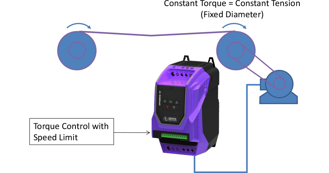
If we’re winding fabric for example, we want to keep constant tension on the take up winder; Torque control will do that, providing the diameter is constant. If we measure or calculate the roll diameter, we can adjust the torque setpoint accordingly. In winder applications it is usual to set a speed limit, because if the material runs out or breaks, the drive will try to maintain torque by speeding up, which can be quite exciting.
Sometimes we use torque control in a mixer application where the consistency changes and we want to run the mixer as fast as possible, slowing down maybe as the mixture thickens.
Drives will often operate in speed control, but with a torque limit; if the load unexpectedly rises, the torque control takes over from speed control and controls accordingly. This can protect the process from overload and damage. This can be used to replace ‘shear pins’ that perform the same function mechanically. Remember, at any one time you can control Torque or Speed, but not both.
Another application for torque control is where multiple drives are mechanically connected, and we want to share the load across the motors. An example might be a long conveyer with several drives and motors, and shown in Figure 2.
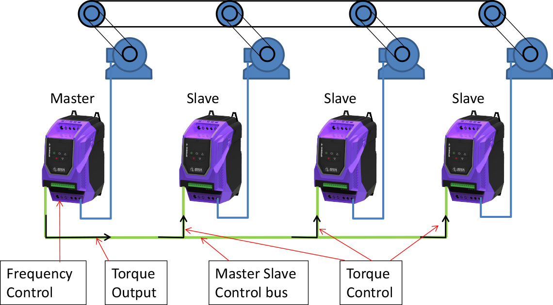
Here, we run the first motor in normal speed control and take the analogue output from that drive, set up to indicate torque, and connect it to the next drive, running that drive in torque control. Now the two drives should run with the same torque, and therefore the same power (assuming the speeds and scaling are the same). Subsequent drives can be connected in a similar way.
With Invertek drives there is an easier way to run drives together using the master slave connection. Simply connect the drives together using standard Ethernet cable. If you connect more than two drives (up to 63 is possible) you’ll need some T connectors to join the cables. Now change the addresses on the slave drives to something other than the default, and put the slaves into slave mode (P-12 or P1-12). In the simplest mode, which can be done with all Invertek drives, the slaves will run at the same speed as the master, providing they have an enable signal. You can also scale the signal so the drives run at different percentages of the master speed.
A P2 drive has additional features that allow trimming of individual slave speeds using a potentiometer connected to the slave. Speed can be added, subtracted or multiplied depending on the settings. For more information check out Application Note AN-ODP-2-027, on the website at invertekdrives.com.
How about torque control? Again, with P2 we can set up the master slave system so that the torque of the slave drives is controlled from the master.
So although the applications for Torque Control with a single drive are a little specialised, torque sharing is a really useful way of making sure multiple drives share out the load, and Invertek’s master/slave system makes this easy to set up.


